
Types of electrical cables: cross-sections, installation, and how to choose the right one
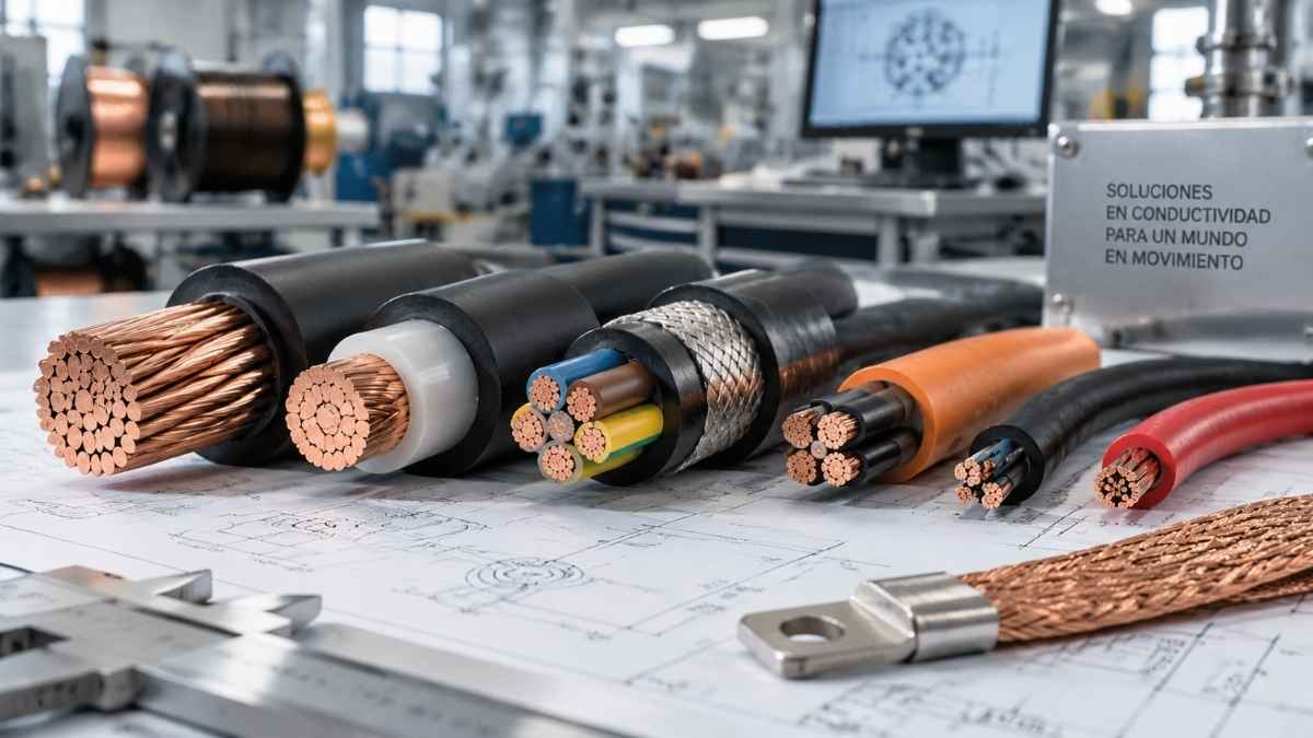
Choosing the wrong type of electrical cable is not just a technical mistake: it can lead to energy losses, premature insulation degradation, unplanned production downtime and fire risks. And yet, conductor selection remains an underestimated decision in many industrial projects.
This guide covers the main types of electrical cables, their classification according to the IEC 60228 standard, cross-section sizing criteria, correct installation methods and special conductors —Litz wire, copper braids and flexible connections— that solve cases where a standard cable is not sufficient.
What is an electrical cable? Components and terminology
An electrical cable is an assembly of one or more metallic conductors surrounded by layers of insulation and protection, designed to safely carry electrical current between two points. Its main components are:
- Conductor: the metallic core through which the current flows. In industrial installations, the standard is Cu-ETP electrolytic copper (minimum purity of 99.9% according to EN 13602) due to its conductivity, ductility and mechanical strength. Aluminium is used in long-distance distribution lines because of its lower weight and cost.
- Primary insulation: the layer surrounding the conductor that prevents electrical contact. The most common materials are PVC (up to 70 °C), XLPE (up to 90 °C), HEPR and silicone for high temperatures.
- Shield / shielding: metallic braid or foil used to protect against electromagnetic interference (EMI). Required in signal and control cables in industrial environments with a high density of equipment.
- Outer sheath (jacket): mechanical and environmental protection for the assembly. PVC, LSZH (halogen-free), neoprene or polyurethane depending on the installation environment.
Classification by voltage: low, medium and high voltage
Rated voltage is the first classification criterion for any cable. It determines the type of insulation, the thickness of the layers and the applicable standards (IEC 60502 family).
Low voltage (LV) — up to 1,000 V
The most widespread category in industrial, commercial and domestic installations. It is subdivided into cables up to 750 V (with thermoplastic and thermosetting coverings for general use) and 0.6/1 kV cables for industrial power installations, designed according to IEC 60502-1, UNE, BS and UL. They are the most commonly used type in electrical panels, machinery and factory distribution.
Medium voltage (MV) — from 1 kV to 36 kV
Distribution from substations to transformer centres. They require XLPE or HEPR insulation with semiconductive screens. IEC 60502-2 standard. Common in industrial parks, renewable energy facilities and railway applications.
High voltage (HV) — from 36 kV
Power transmission from generating stations. Specially constructed cables with thick insulation and metallic armour. IEC 60840 standards (up to 150 kV) and IEC 62067 (above).
Types of cable by industrial application
Within low voltage, there are different families of electrical cables adapted to the specific conditions of each installation. The choice depends on factors such as flexibility, mechanical strength, environmental exposure or the need for protection against interference.
Flexible cables for electrical panels
Flexible cables are designed for the internal wiring of electrical panels, control cabinets and industrial equipment where ease of installation and the ability to adapt to confined spaces are required.
Their construction using multiple fine copper strands allows bends and complex routing while reducing the risk of damage to the conductor or insulation.
Power cables for industrial installations
Power cables are used for the transmission of electrical energy in industrial installations, machinery, motors and low-voltage distribution systems.
They are a common solution in factories and industrial plants where high currents need to be carried safely and reliably over long periods of operation.
Armoured cables
Armoured cables incorporate additional metallic protection, normally made of steel or aluminium. This layer increases their resistance to impacts, mechanical stress, moisture and external damage.
They are particularly used in buried, outdoor and industrial installations or in areas where there is a risk of physical damage to the cable.
Extra-flexible rubber cables
Rubber cables are designed for applications involving continuous movement, vibration or demanding environmental conditions.
The rubber or neoprene sheath provides resistance to oils, abrasion and extreme temperatures, making them common in heavy machinery, welding equipment, cranes and mobile systems.
LSZH halogen-free cables
LSZH (Low Smoke Zero Halogen) cables are designed to reduce the emission of dense smoke and corrosive gases in the event of fire.
They meet specific requirements such as IEC 60754, related to the emission of acidic gases, and IEC 61034, relating to smoke density.
They are particularly important in public buildings, tunnels, railway installations, data centres and other spaces where the safety of people and equipment is a priority.
Fire-resistant cables
Fire-resistant cables are designed to maintain electrical continuity for a specified period when a fire occurs.
They are used in critical systems such as alarms, emergency lighting, smoke extractors, fire pumps and safety equipment.
Shielded control and signal cables
Shielded control cables allow electrical signals to be transmitted while reducing the impact of electromagnetic interference generated by motors, variable-frequency drives or other industrial equipment.
They are commonly used in industrial automation, PLC systems, sensors and smart machinery.
Photovoltaic cables
Cables used in solar installations must withstand demanding environmental conditions: ultraviolet radiation, moisture, temperature changes and prolonged outdoor exposure.
Their specific design ensures the reliability of photovoltaic installations throughout their service life, following standards such as IEC 62930.
Flexibility and IEC 60228 classes
The IEC 60228 standard classifies electrical conductors according to their construction and level of flexibility.
In industrial applications, the most commonly used classes are Class 2, Class 5 and Class 6, as they meet different mechanical requirements.
| Class | Conductor type | Main use |
|---|---|---|
| Class 1 | Single-wire solid conductor | Fixed buried or concealed installations |
| Class 2 | Stranded conductor for fixed installation | Cable trays, conduits, walls and fixed electrical panels |
| Class 5 | Flexible conductor | Machinery, electrical panels and mobile equipment |
| Class 6 | Extra-flexible conductor | Robotics, welding and applications with continuous movement |
The flexibility of a cable depends mainly on the number of strands forming the conductor and the individual diameter of each one. The greater the number of strands and the smaller their diameter, the greater the cable’s flexibility.
Class 6 conductors are designed to withstand repetitive movements and smaller bending radii than conventional cables, making them suitable for industrial robots, mobile equipment and systems subjected to continuous movement cycles.
Casa Masfarné manufactures flexible cables and extra-flexible cables with Class 5 and Class 6 Cu-ETP conductors, available in cross-sections from 0.50 mm² to 600 mm², in both bare and tinned copper.
Cable cross-section: how it is measured and how to choose it
The conductor cross-section, expressed in mm², is one of the most important parameters for determining the current-carrying capacity of an electrical cable.
An appropriate cross-section helps prevent overheating, energy losses and operating problems in the installation.
To correctly select the cross-section of a conductor, three main factors must be analysed:
- Maximum expected current: the current that will flow through the conductor during normal operation.
- Permissible voltage drop: the voltage loss caused by the resistance of the cable itself and the length of the circuit.
- Short-circuit current: the conductor’s ability to withstand a temporary overcurrent until the protection devices operate.
The final cross-section must always be the most demanding one after checking these three criteria.
Indicative table of cross-section, current and application
| Cross-section | Approximate current | Typical application | IEC 60228 class |
|---|---|---|---|
| 0.50 mm² | 3 A | Signal, automation and electronic equipment | Class 5 / 6 |
| 1.5 mm² | 15 A | Lighting and auxiliary circuits | Class 5 |
| 2.5 mm² | 21 A | Power outlets and power circuits | Class 5 |
| 4 mm² | 27 A | Small motors and light industrial installations | Class 5 |
| 6 mm² | 34 A | Medium-sized motors and industrial branch circuits | Class 5 |
| 10 mm² | 46 A | Workshop lines and industrial power supply | Class 5 |
| 16 mm² | 61 A | Main electrical panels and large motors | Class 2 / 5 |
| 25 mm² | 80 A | Industrial power distribution | Class 2 / 5 |
| 35 mm² | 99 A | Main industrial lines and factory distribution | Class 2 |
| 50–95 mm² | Up to 170 A | Main feeders and low-voltage distribution | Class 2 |
| 120–400 mm² | More than 200 A | High power, industrial service connections and generation | Class 2 |
| 0.05–1 mm² (braid) | Variable | Equipotential earthing, EMC shielding and flexible connections | Class 5 / 6 |
Equivalent AWG system
In markets such as the United States, Canada and Mexico, the AWG (American Wire Gauge) system is commonly used to identify conductor cross-sections.
Unlike the metric system, in AWG a higher number corresponds to a thinner conductor. As a reference, an AWG 22 cable is approximately equivalent to 0.34 mm², while an AWG 4/0 is approximately equivalent to 107 mm².
For international projects, it is important to always check the exact equivalence between both systems before selecting a conductor.
6. Types of insulation and outer sheath
The insulation of an electrical cable does more than prevent accidental contact. It also determines its maximum operating temperature, chemical resistance, fire performance and durability under different environmental conditions.
PVC (polyvinyl chloride)
PVC is one of the most widely used materials in electrical cables due to its balance of cost, resistance and ease of manufacturing.
Its usual operating temperature reaches approximately 70 °C. Its main limitation arises in the event of fire, as it can generate corrosive halogenated gases and a high amount of smoke.
XLPE (cross-linked polyethylene)
XLPE offers better thermal performance than PVC, normally allowing operation at up to 90 °C in continuous service.
It also provides good resistance to water, ultraviolet radiation and different environmental conditions, which is why it is widely used in industrial power and medium-voltage cables.
LSZH (halogen-free)
LSZH materials are designed to minimise the emission of corrosive gases and dense smoke in the event of fire.
They are particularly important in installations where personal safety and the protection of electronic equipment are priorities, such as tunnels, airports, hospitals, data centres and railway systems.
Silicone, Kapton® and Nomex® for high temperatures
Some applications require cables capable of operating in high-temperature environments. Special materials such as silicone, Kapton® or Nomex® are used for these cases.
Kapton®, based on polyimide, can be used in applications at temperatures of up to approximately 300 °C.
Nomex®, based on aramid fibre, withstands temperatures close to 180 °C and is commonly used as outer insulation in certain high-frequency applications.
Neoprene and polyurethane
Neoprene and polyurethane coverings are designed for cables subjected to demanding mechanical conditions.
They provide resistance to abrasion, oils, solvents and outdoor exposure, making them common in industrial machinery, mobile equipment, welding and port applications.
7. Correct installation: technical criteria that make the difference
A correctly selected cable can fail if the installation does not comply with its intended operating conditions.
The IEC 60364-5-52 standard establishes different installation methods and correction factors that must be considered during sizing.
Minimum bending radius
Bending a cable below the recommended bending radius can damage the insulation, deform the conductor or reduce its service life.
As a general reference, flexible cables installed in fixed applications usually require bending radii of approximately 6 to 8 times their outer diameter.
In applications involving continuous movement, this value can increase to approximately 8–12 times the outer diameter, depending on the cable design.
Ambient temperature and correction factors
The current-carrying capacity of a cable depends directly on the ambient temperature.
Current-carrying capacity tables are usually calculated for an ambient temperature of 30 °C. As the temperature increases, the cable loses heat dissipation capacity and it may be necessary to increase the conductor cross-section.
Cable grouping
When several cables are installed together in trays, pipes or conduits, the heat generated by each one affects the others.
For this reason, correction factors must be applied to reduce the maximum permissible current. The greater the concentration of cables along the same route, the greater the required reduction.
Installation method and its effect on cross-section
- Installation in free air: allows optimum heat dissipation and provides the highest current-carrying capacity.
- Perforated cable tray: provides good ventilation, although it may slightly reduce capacity compared with a completely open installation.
- Pipe or conduit: provides lower heat dissipation and may require a larger cross-section.
- Buried installation: depends on factors such as the thermal resistivity of the soil and environmental conditions.
Voltage drop
In installations with long cable runs, voltage drop can be the determining factor when selecting a larger cable cross-section.
A commonly used formula for single-phase circuits is:
ΔV = 2 × L × I × ρ / S
Where:
- L: conductor length in metres.
- I: electrical current in amperes.
- ρ: copper resistivity (approximately 0.017 Ω·mm²/m at 20 °C).
- S: conductor cross-section in mm².
Correctly controlling voltage drop ensures that equipment operates within its intended parameters and avoids unnecessary energy losses.
8. Colour identification according to IEC 60446
Correct identification of electrical conductors is essential to ensure safety during installation, maintenance and technical inspections.
The IEC 60446 standard establishes colour identification criteria to facilitate the interpretation of electrical circuits.
| Colour | Function | Standard | Application |
|---|---|---|---|
| Brown / Black / Grey | Phase (L1, L2, L3) | IEC 60446 | Single-phase and three-phase systems in Europe |
| Blue | Neutral (N) | IEC 60446 | Neutral conductor identification |
| Green-Yellow | Earth / PE | IEC 60446 | Protective conductor |
| Black / Red / Blue | Phase (L1-L3) | NEC | Common configurations in North America |
| White | Neutral | NEC | Functional equivalent of European blue in certain markets |
In international projects, it is especially important to check the regulations of the destination country. European and North American colour codes do not always match, so additional identification using labels may be necessary to prevent errors during installation or maintenance.
9. Special conductors: Litz wire, copper braids and flexible connections
There are industrial applications where a conventional cable does not provide the required performance. In these cases, conductors specifically designed to meet particular electrical or mechanical requirements are used.
These solutions include Litz wire, copper braids and custom electrical connections.
Litz wire: a solution for high-frequency applications
When alternating current operates at high frequencies, the phenomenon known as the skin effect occurs.
This phenomenon causes the current to tend to flow through the outer region of the conductor, reducing the effective cross-section used and increasing electrical losses.
From approximately 10 kHz, this effect can become relevant in certain power and high-frequency applications.
Litz wire reduces these losses through a structure made up of multiple fine copper strands that are individually insulated and twisted according to a specific geometry.
Thanks to this construction, each strand occupies different positions within the conductor, resulting in a more uniform distribution of current.
Its main applications include:
- Transformers for switched-mode power supplies.
- Wireless inductive charging systems.
- Resonance coils.
- Magnetic resonance equipment.
- Railway traction systems.
- Filters and solutions for electromagnetic interference.
Casa Masfarné manufactures Litz wires with individual wire diameters from 0.05 mm and solutions adapted to high-frequency applications between 10 kHz and 5 MHz.
Copper braids: flexibility, earthing and shielding
Copper braids consist of multiple fine copper strands braided together.
Their construction provides high mechanical flexibility, resistance to vibration and excellent adaptability in spaces where a rigid conductor would not be suitable.
Their most common applications are:
- Earthing and equipotential bonding connections: connections between metal parts, structures and earth bars.
- EMC shielding: protection against electromagnetic interference in signal and control cables.
- Flexible connections in machinery: electrical jumpers in equipment subject to movement or vibration.
- High-current applications: installations where a conventional cable would generate excessive mechanical stress.
Casa Masfarné manufactures flat, square, spiral and shielding copper braids, with cross-sections ranging from 0.75 mm² to 600 mm².
Custom flexible electrical connections
Some industrial, energy or railway installations require solutions that cannot be achieved using standard cables.
In these cases, custom electrical connections are manufactured to suit the geometry, cross-section, terminals and specific conditions of each application.
These connections can incorporate copper braids, flexible cables, conductive foils or specific Litz wire solutions for high-frequency applications.
Casa Masfarné develops flat, round and insulated connections, as well as copper foil solutions of up to 5,000 mm² according to project requirements.
10. Frequently asked questions about electrical cables
What is the difference between a Class 5 flexible cable and a Class 6 extra-flexible cable?
A Class 5 cable is made up of multiple fine strands that make it easier to handle during installation.
A Class 6 cable incorporates even more strands with smaller diameters, providing greater flexibility and resistance to repeated movement cycles.
For this reason, Class 6 cables are commonly used in industrial robots, welding and machinery involving continuous movement.
How is the required cable cross-section calculated?
Correct cross-section selection must take three main factors into account:
- The maximum current that will flow through the conductor, taking temperature and installation method into account.
- The permissible voltage drop depending on the length of the circuit.
- The conductor’s ability to withstand a short-circuit current until the protection devices operate.
The final cross-section will always be the most restrictive one after carrying out these calculations.
When is it necessary to use Litz wire?
Litz wire is mainly used in alternating-current applications where high frequencies cause significant losses due to the skin effect.
In conventional low-frequency applications, standard flexible cables are usually sufficient, whereas in high-frequency systems Litz wire can improve electrical performance.
What is the difference between bare copper and tinned copper?
Bare copper is the standard solution for most electrical applications.
Tinned copper incorporates a surface layer of tin that improves resistance to oxidation and corrosion, especially in humid or marine environments or where chemical agents are present.
It also facilitates certain soldering processes and improves the stability of electrical contact in some applications.


