
C1100 copper (Cu-ETP): properties, uses and international equivalents
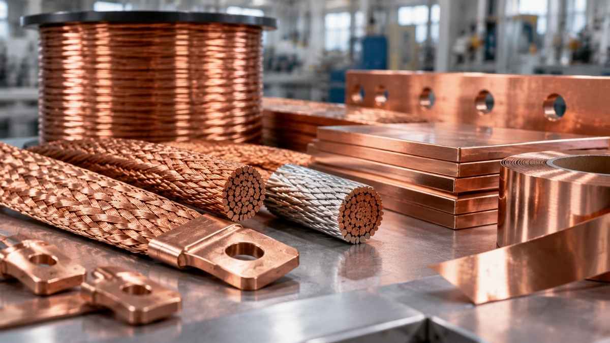
A flexible copper braid may look like a simple component. It is copper, grouped together, with terminals. But behind a braid that withstands 30 years of repeated bending in an electrical cabinet, or that carries 2,000 A in a substation busbar without a hot spot, there are seven linked process steps in which every decision — wire gauge, braiding direction, type of termination — has direct consequences on in-service performance.
This article describes the complete process, as carried out in a European factory, and the technical variables controlled at each stage.
Raw material: C1100 copper wire
The starting point is C1100 electrolytic copper wire (Cu-ETP) supplied in high-capacity coils. The raw material arrives in standard gauges — normally between 8 and 10 mm in diameter — and undergoes incoming inspection: composition certificate (minimum 99.90% Cu), conductivity verification (100% IACS), visual surface inspection and tensile testing to confirm the metallurgical condition.
When required by the application, the wire is specified as tinned from the outset: coated by immersion in a tin bath with a typical thickness of 2–5 μm. Tinning can be applied to thick wire before drawing or to the final strand; each option has advantages and trade-offs that are decided according to the customer’s specifications.
Step 1 — Wire drawing
The initial thick wire cannot be braided directly. It must be reduced to the individual strand gauge — typically between 0.10 mm and 0.50 mm depending on the application — by passing it through a series of diamond or tungsten carbide dies with progressively smaller diameter openings.
Drawing is carried out on multi-pass machines (15- to 25-pass wire drawing machines) with continuous emulsion cooling. Each pass reduces the cross-section by 15–20% and hardens the material through plastic deformation. At the end of the process, the copper is cold-worked and has lost ductility — it requires subsequent treatment.
Step 2 — Strand annealing
The drawn strands undergo annealing in a continuous or bell furnace, in a controlled atmosphere (nitrogen or cracking gas) to prevent oxidation. Temperatures are in the 400–600 °C range for calculated periods to achieve the required final ductility.
Annealing restores the crystalline structure of the copper, eliminates work hardening and returns elongation to 30–50%. This step is what allows the final braid to withstand hundreds of thousands of bending cycles without cracking.
Step 3 — Stranding or cabling
The individual annealed wires are grouped into small bundles — called “strands” or “cords” — using stranding machines. A typical cord groups between 7 and 37 wires with a calculated lay length (helix length per turn) that determines the flexibility and compaction of the bundle.
Lay length is a critical variable. A short lay provides greater flexibility but reduces the effective cross-section because the wires travel a longer path. A long lay provides a greater effective cross-section but less flexibility. Short lays are preferred for equipotential connections in electrical cabinets; long lays are preferred for large-section braids with little flexing.
Step 4 — Braiding
The cords are taken to the braiding machine, which is the machine that gives the product its name. An industrial braider has rotating spindles (typically 16, 24, 32 or 48 spindles), each carrying a cord bobbin. The spindles rotate in two opposite directions, forming a crossed helical weave around a central axis.
Three final characteristics depend on the braiding process:
- Braiding density, measured in crossings per centimetre. The higher the density, the more compact and dimensionally stable the braid, but also the more rigid.
- Braiding angle, which determines the relationship between braid length and the length of wire used.
- Braiding direction (S or Z, depending on the inclination), which can be relevant in applications involving torsion.
Step 5 — Forming to the final geometry
The braid leaves the braiding machine with a circular cross-section. For many applications, this is the final geometry — it is the typical construction of round braids.
When the customer requires another geometry, the braid undergoes a forming process:
- Flattening by rollers to obtain flat braids, with a width/thickness ratio between 3:1 and 10:1
- Squaring using forming rollers to produce stackable square braids
- Tubular forming with a hollow inner core for spiral braids with high multi-axis flexibility
Forming is carried out cold and adds a certain amount of residual hardening that must be compensated for during sizing.
Step 6 — Termination: soldering, crimping or terminal fusion
A braid without terminals has little practical application. The ends must be fitted with connectors so that they can be bolted to the busbar, equipment or receiving element. There are three main techniques:
Crimping. A copper terminal — typically tinned — is placed over the stripped end of the braid and compacted using a hexagonal or square press. The terminal mechanically deforms the strands until intimate contact is achieved. It is the fastest and most economical method and covers most standard industrial applications.
Resistance or induction soldering. Localised heat is applied to the braid + terminal assembly until a tin or silver solder filler melts and creates a metallurgical bond. It is slower, but produces a joint with lower electrical resistance and no risk of loosening due to vibration.
Terminal fusion (cold welding / fusion). In large-section braids, the wires at the end are fused together to form a solid block that acts as an integrated terminal. It can subsequently be machined or drilled. It provides the lowest possible contact resistance and is specified in high-current special connections.
Step 7 — Insulation and protection (optional)
When required by the application, the finished braid is insulated with heat-shrink tubing, PVC tubing, silicone or specific materials according to the required thermal class. This is the manufacturing process used for insulated connections and braids intended for environments with human contact or arc risk.
For EMC applications, shielding braids can be manufactured in which the braid itself is installed as shielding over an existing cable.
Step 8 — Quality control and testing
Each manufactured batch undergoes testing before dispatch. The usual tests are:
- Electrical resistance measured in micro-ohms between terminals, compared with the theoretical value according to cross-section and length
- Tensile test of the braid-terminal assembly, with minimum load according to the applicable standard
- Flexing test over repeated cycles for braids intended for dynamic applications
- Heating test under rated current, verifying that the stabilised temperature does not exceed the limits
- Visual and dimensional inspection of 100% of the batch
Upon request, certificates are issued with the individual results for each braid — mandatory in railway, defence and some energy applications.
Applicable standards
Flexible copper braids are manufactured and tested according to different standards depending on the sector:
- UNE-EN 13600 — Copper and copper alloys. Copper wire for electrical purposes
- UNE-EN 60228 — Conductors of insulated cables
- NF C 20-540 — French standard applicable to railway applications
- DIN 46440 / 46441 — Crimped cable terminals
- NFF 61-020 — French railway standard
Frequently asked questions
How long does a flexible copper braid last in service?
Under nominal conditions and with correct sizing, a flexible braid has a service life equivalent to that of the equipment in which it is installed — 20 to 40 years are common values in electrical cabinets and substations.
Can a damaged braid be repaired?
The terminal can be replaced if it is damaged. If the braid has cracks or broken wires due to fatigue, the entire braid must be replaced — it cannot be repaired.
What is the difference between a braid and a flexible cable?
A braid has wires woven in a crossed helical pattern (“braiding machine” construction). A flexible cable has wires stranded in a parallel helix (“stranding machine” construction). The braid is more compact and dimensionally stable; the flexible cable is more flexible per unit of cross-section.
Why are some braids tinned and others not?
Tinning protects the copper from oxidation and facilitates terminal soldering. It is specified in environments with humidity, saline atmospheres or sulphur compounds. In dry indoor installations, bare copper performs without problems.
Can custom braids be manufactured?
Yes. Cross-section, length, terminal type, insulation and finish can all be customised. At Masfarné, they are manufactured to order according to the customer’s technical specifications.
Conclusion and next step
Behind every flexible braid there are eight process steps where the right technical decision results in a component that lasts for decades, while the wrong decision leads to early failure. At Masfarné, we have been manufacturing flexible braids and special connections to technical specifications for more than 40 years, with individual batch controls and full customisation capability.
Do you need a custom-made flexible braid? Tell us about your project


