
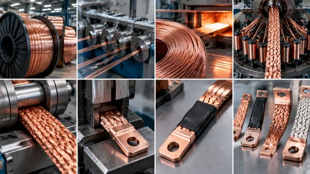
How a flexible copper braid is made: a step-by-step process
In any power electrical panel — from low-voltage switchgear to the main busbar of a substation — copper is distributed along two different paths. Sections that carry current in a straight and stable line are handled with a rigid busbar. Sections that absorb movement, expansion or vibration are handled with a flexible connection. And a large proportion of panel maintenance problems arise precisely where someone made the wrong choice between these two options.
This article compares the two types, explains when the designer chooses each one and describes the hybrid cases where they coexist.
What is a busbar and what function does it perform
A busbar is the system of rigid conductors that distributes electrical current inside a panel or enclosure, from the incoming supply to the outgoing connections to the different protected circuits. It has three functions:
- Carry the rated current without exceeding the permissible temperature
- Withstand the electrodynamic forces of a short circuit without deforming
- Maintain insulation distances between phases and with respect to earth
In industrial low voltage, the busbar is almost always made from copper bars — sometimes aluminium — bolted to insulating supports. In medium voltage and substations, the geometry becomes more complex and tubes, profiles or special busbars are used.
Rigid copper busbar — characteristics and typical use
A rigid busbar is a rolled copper bar with a rectangular cross-section, in a hard or semi-hard state, with standardised dimensions (typically between 12×2 mm and 100×10 mm in industrial panels, larger in substations).
Its advantages:
- High current-carrying capacity per unit cost
- Good heat dissipation due to its large external surface area
- Easy to machine (holes, gentle bends) and bolt
- Dimensionally stable, does not require intermediate supports over short sections
Its limitations:
- Absolute rigidity: it does not absorb any movement, expansion or vibration
- Any deformation is transmitted entirely to the connection points, with the risk of bolts loosening
- Laborious installation when the geometry of the panel requires multiple bends
- Coplanarity defects between the busbar and equipment generate permanent mechanical stresses
Typical application: distribution in main panels, vertical column busbars, connections between equipment aligned on the same frame.
Flexible copper connection — characteristics and typical use
A flexible connection replaces the rigid busbar over a specific section with a construction that absorbs movement. The three usual constructions are:
- Flat copper braid: fine braided wires formed into a flat geometry with crimped or fused terminals at the ends
- Laminated flexible busbar: a pack of thin copper sheets (0,1-0,5 mm thick each) stacked and joined only at the ends, allowing relative movement between the sheets
- Flat connection with terminals: flat braid with integrated terminals, ready to be bolted directly to the equipment
Its advantages:
- Absorbs thermal expansion from neighbouring rigid conductors
- Absorbs mechanical vibration (transformers, motors, switchgear with frequent operation)
- Compensates for misalignment between equipment and busbar without transmitting stresses
- Facilitates the removal and maintenance of individual equipment
- Absorbs slight movements caused by settling of the panel or floor
Its limitations:
- Higher unit cost than an equivalent rigid busbar
- Requires correctly executed terminals — poor crimping is the most common failure
- Occupies more volume than a rigid busbar with the same electrical cross-section
Direct technical comparison
| Parameter | Rigid busbar | Flexible connection |
|---|---|---|
| Thermal expansion absorption | None | High |
| Vibration absorption | None | High |
| Misalignment compensation | No | Yes |
| Cost per metre (same cross-section) | Base | 2,5–4× higher |
| Ease of installation in complex geometries | Low | High |
| Heat dissipation | Very good | Good |
| Maintenance of tightening torque | Requires periodic inspection | Retained better |
| Durability under dynamic operation | Poor (fatigue at joints) | Good |
Thermal expansion: the main reason for including flexible connections
Copper has a linear expansion coefficient of 17,7 × 10⁻⁶ /°C. A 3-metre section of rigid busbar that goes from an ambient temperature of 20 °C to an operating temperature of 90 °C expands by:
ΔL = 3.000 mm × 17,7 × 10⁻⁶ × 70 = 3,72 mm
Almost 4 millimetres. If that section is rigidly bolted at both ends, those 4 mm have nowhere to go — they become mechanical stress that:
- Loosens bolts due to cyclic deformation
- Deforms insulating supports due to lateral stress
- Can crack the busbars themselves in areas with the highest stress concentration
The standard solution is to insert a flexible connection every 2-3 metres of rigid busbar, or at every point where the busbar connects to equipment whose mass makes it immovable (transformer, power circuit breaker, industrial rectifier). The flexible connection absorbs expansion and mechanically decouples the sections.
Common hybrid cases in industrial panels
Transformer-main busbar connection. The transformer secondary represents a considerable thermal and mechanical mass. Its connection to the low-voltage busbar is always made using flexible connections — normally flat braids with terminals — to decouple expansion and absorb the vibration of the transformer itself.
Connection to withdrawable circuit breaker. Circuit breakers with a withdrawal function require connections that tolerate insertion-withdrawal movement and the mechanical tolerances of the connected position. This is achieved with short flexible connections between the breaker contacts and the fixed busbar.
Links between columns in a modular panel. When the main busbar crosses from one column to another in a modular panel, small relative movements between columns caused by transport, assembly and settling are absorbed by flexible connections at the transition points.
Connection to rectifier or power converter. Power electronics equipment operates at high temperatures and with medium-frequency mechanical vibrations. It is always connected to the busbar using flat braids.
Compensation over long sections. In continuous busbars longer than 6-8 metres, expansion compensators are inserted at intervals, implemented using short flexible connections.
How to choose the right flexible construction
Once it has been decided that the section will be flexible, the specific choice depends on the geometry and amperage:
- Low and medium amperages (up to 400 A), standard installation: tinned flat braid with crimped terminals
- High amperages (400-2.000 A): laminated flexible busbar or large-cross-section flat braid with fused terminals
- Very high prospective short-circuit current: construction with integral fused terminals, avoiding the crimped connection due to better heat conduction during the fault
- Aggressive environment (chemical, marine, outdoor railway): always tinned, with additional heat-shrink protection where applicable
- EMC requirement: consider a complementary shielding braid over the power connection
For electrical cross-section sizing, the same criteria are applied as for any flexible braid — permissible current corrected for ambient temperature and grouping, short-circuit verification and voltage drop verification. The sizing guide that we publish separately covers the complete method.
Common busbar mistakes
- Using rigid busbar for the entire busbar system to minimise cost. It saves on materials but increases the cost of tightening inspections every six months and cyclic failures due to fatigue.
- Using a flexible connection where there is no movement. Additional cost with no benefit. A stable, short and aligned section is handled with a rigid busbar.
- Incorrect sizing of the flexible connection terminal. The terminal is the electrically critical point. A terminal with insufficient cross-section creates a thermal bottleneck that degrades the joint over time.
- Failing to allow space for the flexible connection in the panel design. The flexible connection occupies more volume than the equivalent rigid busbar. If the designer does not take this into account, the geometry ends up being forced in ways that eliminate the flexibility of the component itself.
- Mixing aluminium and copper without a bimetallic connection. Direct connection between an aluminium busbar and a copper terminal causes galvanic corrosion within a few years. Specific bimetallic terminals are required.
Frequently asked questions
What rigid busbar cross-section is equivalent to a flexible connection of X mm²?
The electrical cross-section is equivalent if the usable copper is the same. A 240 mm² flat braid is electrically equivalent to a 240 mm² rigid copper busbar. The difference lies in the geometry: the braid occupies more external volume and dissipates heat slightly differently.
Can an existing rigid busbar be replaced with a flexible connection without changing the rest of the panel?
Yes, provided that the electrical cross-section and insulation distances are maintained, and provided that the flexible connection terminals are compatible with the existing bolts. It is a common corrective maintenance intervention in panels with heating problems caused by fatigue at joints.
Does a flexible connection produce more Joule-effect losses than a rigid busbar?
No, if they are correctly sized. The resistance of copper is the same. Any incremental losses are at the terminals — and with correctly executed terminals they are negligible.
How many flexible connections does a standard electrical panel need?
It depends on the topology. In a typical industrial low-voltage panel, they are installed at least at the transformer connection, at each withdrawable circuit breaker and at transition points between columns. In more complex panels, all points where the busbar connects to individual equipment of a certain mass are handled with flexible connections.
Can custom flexible connections be manufactured for special geometries?
Yes. Length, cross-section, terminal type, insulation and finish are fully customisable. This is standard practice in project-specific panels — each connection is manufactured to specification with the exact dimensions of the available space.
Conclusion and next step
The decision between rigid busbar and flexible connection is not a matter of cost: it is a matter of what is happening mechanically at that point in the panel. Where there is movement, expansion or vibration, the flexible connection is the only solution that ages well. Where there is a stable and aligned section, the rigid busbar is the correct option.
At Masfarné, we manufacture flat braids, flat connections with terminals and custom flexible connections for industrial busbars, according to technical specifications and with crimped, soldered or fused terminals depending on the application.
Do you need custom flexible connections for a panel or busbar? Tell us about the project


