
Parts of an electrical cable: A comprehensive technical guide
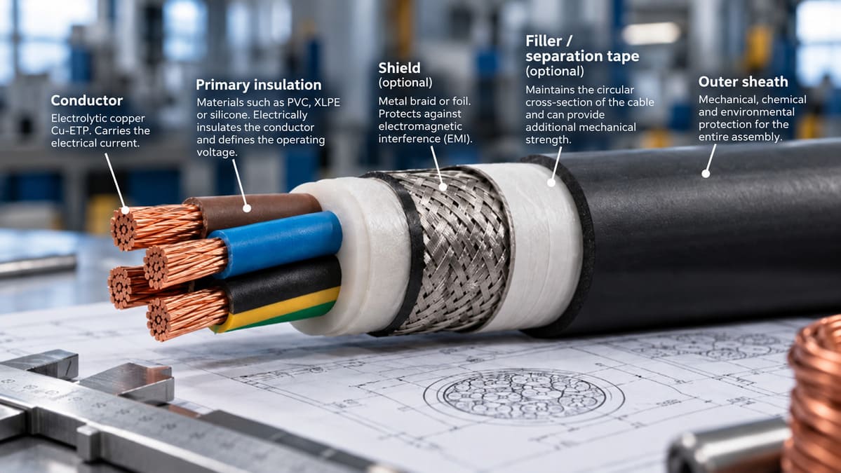
An electrical cable is not simply “a copper wire with plastic around it.” Each layer that makes it up has a specific technical function, is manufactured from a material selected for specific reasons, and must comply with international standards that determine its performance under real operating conditions.
Knowing the parts of an electrical cable and understanding what each one does is the starting point for correctly specifying a conductor, identifying why a cable fails earlier than expected, and choosing between the options available on the market based on real technical criteria —not just price or brand.
This guide describes in detail each component of an industrial electrical cable: the conductor, primary insulation, shielding, filler and outer sheath. It includes comparative material tables, reference standards and the criteria that determine the choice of each element depending on the application.
1. Overview: the layers of an electrical cable
The structure of an industrial electrical cable can be visualised as a system of concentric layers, each with a different function. From the inside out:
| Layer | Function |
|---|---|
| Conductor | The metallic core. It carries the electrical current. |
| Primary insulation | Surrounds the conductor. Prevents electrical contact and defines the operating voltage. |
| Shield (optional) | Metal braid or foil. Protects against electromagnetic interference (EMI) or contains the electric field in medium- and high-voltage cables. |
| Filler / separator tape (optional) | Maintains the circular cross-section of multi-core cables. It can also provide additional mechanical strength. |
| Outer sheath | The outermost layer. Provides mechanical, chemical and environmental protection for the entire cable. |
Not all cables include all these layers. A shielded signal cable may have up to six distinct layers. A bare earth conductor has only the conductor. A Litz wire has the conductor, the individual enamel insulation of each strand and the overall insulation —with no outer sheath in many applications. The complexity of the cable always reflects the requirements of its final application.
2. The conductor: material, structure and flexibility classes
The conductor is the active element of the cable: the part that actually carries the electrical current. Its two fundamental design parameters are the material and the structure (the number and diameter of the strands that make it up).
2.1 Conductor material
Cu-ETP electrolytic copper (according to EN 13602) is the reference material in industrial installations. With a conductivity of 58 MS/m —the highest among metals used industrially— and a minimum purity of 99.9%, it offers the best combination of conductivity, ductility and mechanical strength available on the market. The electrolytic production process guarantees uniform purity throughout the entire length of the conductor.
Tinned copper (CuSn) incorporates a surface layer of tin that improves resistance to corrosion and oxidation —critical in humid, marine environments or where sulphurous vapours are present— and improves the solderability of the ends. According to EN 13602, the coating thickness is classified into three grades (A, B and C), with minimum thicknesses of 0.30 µm, 0.60 µm and unspecified respectively.
| Material | Conductivity (MS/m) | Main advantages | Limitations / typical use |
|---|---|---|---|
| Cu-ETP electrolytic copper | 58.0 | Maximum conductivity, ductility, solderability, mechanical strength | Higher cost than aluminium; standard across almost all industries |
| Tinned copper CuSn | ~56.0 | Resistance to corrosion and oxidation; excellent solderability | Slight reduction in conductivity; use in humid and marine environments |
| Aluminium (Al) | 35.5 | Low weight and cost; widely used in overhead distribution lines | Lower conductivity; requires a larger cross-section; more complex connections |
| Silver-plated copper CuAg | ~58.5 | Resistance to oxidation at high temperatures; high frequency | Very high cost; aerospace and critical high-frequency applications |
2.2 Conductor structure: IEC 60228 classes
The conductor structure —whether it consists of a single solid wire or multiple fine stranded wires— determines its mechanical flexibility. The IEC 60228 standard classifies conductors into four classes:
- Class 1 (solid conductor): a single copper wire. Maximum rigidity. Fixed buried or concealed installations. Not suitable for repeated bending.
- Class 2 (stranded conductor for fixed installation): several thick stranded wires. For cable trays, conduits or concealed installation in walls. Allows installation with bends, but not continuous movement.
- Class 5 (flexible): multiple fine strands. Can be bent and handled without deterioration. The standard for machinery wiring, electrical panels and mobile equipment.
- Class 6 (extra-flexible): a greater number of even finer strands. Smaller minimum bending radius. For robots, welding, service cables and any application involving continuous high-frequency movement.
Design rule: the greater the number of strands and the smaller their individual diameter, the greater the mechanical flexibility and resistance to bending fatigue. A Class 6 cable can withstand tens of millions of bending cycles; a Class 1 conductor will fracture under repeated bending.
2.3 The conductor in Litz wire: a special case
Litz wire takes the logic of Class 6 to the extreme: multiple ultra-fine wires (from 0.05 mm in diameter), individually enamelled and stranded in a specific geometry. The objective is not only flexibility but also uniform current distribution at high frequencies, counteracting the skin effect, which at frequencies above 10 kHz confines current to the surface of the conductor and significantly increases resistive losses.
More information: Litz Wire — Casa Masfarné
3. Primary insulation: materials and operating temperatures
Primary insulation is the layer that directly surrounds the conductor. Its function is to prevent electrical contact between the conductor and any surrounding element —other conductors, the shield, the sheath or installation surfaces— and to define the cable’s rated operating voltage.
The insulation material determines the cable’s maximum operating temperature (and therefore its current-carrying capacity), dielectric strength, cold flexibility and behaviour in the event of fire. There is no universally superior material: each has an optimum range of applications.
| Material | Max. temp. | Reference standard | Key properties | Typical application |
|---|---|---|---|---|
| PVC | 70 °C | IEC 60502 | Low cost, versatility | General use, electrical panels, standard domestic and industrial installations |
| XLPE (cross-linked polyethylene) | 90 °C | IEC 60502 | Resistance to water and UV, low permittivity | MV/HV, demanding industrial LV, photovoltaic systems |
| HEPR | 90 °C | IEC 60245 | Mechanical and chemical resistance | Industrial rubber cables, heavy machinery |
| LSZH (low-smoke zero-halogen) | 70–90 °C | IEC 60754 | Halogen-free, low smoke emission | Tunnels, railways, aerospace, public spaces |
| Silicone | 180 °C | IEC 60245 | High flexibility at low temperatures, thermal resistance | Ovens, motors, high-temperature industrial lighting |
| Kapton® (polyimide, PI) | 300 °C | — | Extreme chemical and thermal resistance | Aerospace, medical equipment, high frequency (Litz wire) |
| Nomex® (aramid) | 180 °C | — | Dielectric strength, low moisture absorption | Outer insulation in Litz wire, dry-type transformers |
Important note: the maximum permissible current of a cable depends not only on the conductor cross-section, but also on the maximum operating temperature of the insulation. A cable with XLPE insulation (90 °C) can carry more current than the same conductor with PVC insulation (70 °C) because it can dissipate more heat without degrading. Therefore, two cables with the same cross-section in mm² but different insulation types are not directly interchangeable: their ampacity tables are different (IEC 60364-5-52).
Insulating enamel in Litz wire
In Litz wire, the primary insulation of each individual strand is not an extruded thermoplastic layer, but a polymer enamel applied in very thin layers (typically 3–5 µm). The most common enamels are polyurethane (solderable at low temperatures, used in wireless chargers and signal transformers) and polyester-imide or polyimide (higher thermal resistance, for power transformers and traction systems). The choice of enamel is one of the most critical design parameters in a Litz specification.
4. Electromagnetic shielding: when it is needed and which type
The shield is a conductive layer —generally a tinned copper braid, aluminium foil or a combination of both— that surrounds the primary insulation. Its function depends on the type of cable:
- In signal and control cables: it protects the transmitted signal against external electromagnetic interference (EMI). The shield is connected to earth at one end and acts as a Faraday cage.
- In medium- and high-voltage cables: it contains the electric field generated by the conductor within the cable geometry, preventing partial discharges towards the outside and ensuring uniform field distribution.
- In coaxial and RF cables: it simultaneously acts as the current return path and as a shield against electromagnetic radiation.
Types of shielding and their effectiveness
- Tinned copper wire braid: typical coverage of 85–98%. High flexibility. The standard for industrial control and signal cables. Allows movement without deterioration of the shield.
- Aluminium foil (Al-Pet): 100% coverage. More economical. Less flexible —not recommended for moving cables. It is used in combination with a copper drain wire to facilitate the earth connection.
- Combined braid + foil: the standard for cables with demanding EMC requirements. Full coverage with the flexibility of the braid. Common in railway, aerospace and medical applications.
- Semiconductive shield (MV/HV cables): this is not metallic, but rather a layer of semiconductive compound applied above and below the XLPE insulation, which homogenises the electric field and eliminates partial discharges.
Masfarné shielding braids are manufactured from bare or tinned Cu-ETP with coverage ranging from 85% to 98%, across a wide range of cross-sections. More information: Copper Braids — Casa Masfarné
5. Filler and separator tape
In multi-core cables —those that group several insulated conductors within a single sheath— the space between the conductors cannot simply be left empty. This is where filler materials and separator tapes come into play.
The filler
The filler has two functions: maintaining the circular cross-section of the cable (essential for the sheath to provide uniform protection and for the cable to pass correctly through conduits or cable glands) and providing mechanical stability to the assembly under bending. The most common materials are:
- Polypropylene (PP): the most widely used. Lightweight, good mechanical behaviour, compatible with most insulation materials.
- Nylon or polyamide: greater mechanical strength. For industrial cables with severe mechanical requirements.
- Flame-retardant compounds: in LSZH cables, the filler must also meet halogen-free requirements.
The separator tape
In cables with an overall shield, a separator tape —generally made of non-woven polyester or kraft paper— is placed between the conductor core and the shield. Its function is to mechanically separate the shield from the conductor insulation, making stripping easier during installation and preventing the metal braid from damaging the insulation during repeated bending.
6. The outer sheath: mechanical and environmental protection
The outer sheath —also known as the jacket— is the outermost layer of the cable. Its function is to protect all the internal layers against the conditions of the installation environment: mechanical damage, chemicals, temperature, UV radiation, moisture and even fire.
The sheath has no direct electrical function, but its deterioration can put the entire installation at risk. A cable with a damaged sheath can absorb moisture, allow short circuits and fail even if the primary insulation remains intact.
| Sheath material | Main resistance | Use environments | Technical note |
|---|---|---|---|
| PVC | General, low cost | Indoors, electrical panels, standard industry | Produces dense smoke when burning |
| LSZH | Halogen-free | Transport, aerospace, crowded spaces | Mandatory under regulations in many environments |
| Neoprene (CR) | Oils, ozone, UV | Outdoors, heavy machinery, ports | Excellent weather resistance |
| Polyurethane (PU) | Mechanical abrasion | Robots, drag cables, cable carrier chains | Very high resistance to wear caused by friction |
| PTFE / Teflon | Chemicals, temperature | Laboratories, chemical industry, high temperatures | Temperature range: −200 °C to +260 °C |
| CPE / CSPE | Chemical resistance | Chemical industry, offshore applications | Alternative to neoprene in aggressive chemical environments |
Correct selection criterion: using a standard PVC sheath in an installation exposed to oils or solvents can cause it to deteriorate within months. Neoprene or polyurethane have a higher initial cost, but a much longer service life in aggressive environments. The selection criterion must always be the actual installation environment: temperature, chemicals present, risk of abrasion and fire-performance requirements.
7. How to read electrical cable designations
The technical designation of an electrical cable encodes all the information about its construction in a compact format. Although the nomenclature varies between standards (IEC, UNE, BS, VDE), the structure of the designation follows a common logic.
Example of a complete designation: 0.6/1 kV — 3 × 95 + 1 × 50 mm² Cu XLPE PVC Cl. 5
| Position in the code | Example | Meaning |
|---|---|---|
| Rated voltage | 0.6/1 kV | Phase-to-earth voltage / phase-to-phase voltage (kV) |
| No. of conductors | 3 | Number of active conductors in the cable |
| Cross-section | × 95 mm² | Nominal cross-section of each conductor in mm² |
| Neutral conductor | + 1 × 50 mm² | Neutral conductor (cross-section may differ from the phase conductors) |
| Conductor type | Cu | Conductor material (Cu = copper, Al = aluminium) |
| Insulation | XLPE | Primary insulation material |
| Sheath | PVC | Outer sheath material |
| Flexibility class | Cl. 5 | IEC 60228 conductor class |
This structure makes it possible to interpret the construction of a cable unambiguously from its designation. In special cables such as Litz wire, the designation includes additional parameters: number of strands, individual diameter in mm, enamel type and stranding configuration (for example: Litz 200 × 0.10 PU 10 kHz–1 MHz).
8. The special case: conductors without an outer sheath
Not all conductors have an outer sheath. There is an important family of conductors designed for applications where a sheath is either unnecessary or directly undesirable.
Bare copper braids
Copper braids are conductors made from multiple fine strands of braided Cu-ETP without insulation or a sheath. They are mainly used for:
- Earthing and equipotential bonding conductors: where the conductor must make direct contact with the metal parts to be connected.
- Shields and shielding braids: where the braid is applied directly over the cable to be protected.
- Shunts and jumpers in power switchgear: where extreme mechanical flexibility with low electrical resistance is required.
- Connections between moving parts: where the stiffness of a conventional cable would cause accelerated mechanical fatigue.
Litz wire conductors without a sheath
In many high-frequency applications —induction coils, planar transformers and wireless charging antennas— Litz wire is used directly wound around the magnetic core or formed into the coil, without an outer sheath. Mechanical protection is provided by the assembly itself or by encapsulation of the component.
In these cases, the individual insulating enamel on each strand is the only insulation layer, and its properties —enamel melting temperature, dielectric strength and adhesion— are critical design parameters that must be explicitly specified when ordering.
9. Frequently asked questions
How many layers does an electrical cable have?
It depends on the type of cable and its application. A simple low-voltage cable has three layers: conductor, primary insulation and outer sheath. A shielded signal cable may have five or six: conductor, primary insulation, separator tape, shield (braid and/or foil) and outer sheath. A medium-voltage cable adds semiconductive layers above and below the insulation. The number of layers always reflects the requirements of the application.
Which part of the cable determines its maximum operating temperature?
The primary insulation is the component that limits the cable’s maximum temperature. Standard PVC allows operation up to 70 °C; XLPE up to 90 °C; silicone up to 180 °C; and Kapton® (polyimide) up to 300 °C. Continuously exceeding the insulation’s maximum temperature irreversibly degrades it, reduces dielectric strength and can cause short circuits.
Why are some cables shielded and others not?
Shielding is necessary when the circuit transmits signals that are sensitive to external interference (control cables, sensors, instrumentation), when the cable itself may radiate electromagnetic fields that affect other equipment, or when installation standards require it (for example, in railway or aerospace applications). In low-voltage power circuits with no nearby sensitive signals, shielding is generally not necessary.
What is the difference between bare copper and tinned copper in a cable?
Bare copper (Cu) provides maximum conductivity and is the standard for the vast majority of applications. Tinned copper (CuSn) incorporates a surface layer of tin (0.30–0.60 µm depending on the EN 13602 class) that improves resistance to corrosion and oxidation in humid, marine environments or where sulphurous vapours are present, and significantly improves the solderability of the conductor ends. The difference in conductivity between the two is less than 4% and is normally not the deciding factor.
Each layer of an electrical cable exists for a specific technical reason. The conductor defines the current-carrying capacity. The insulation defines the operating voltage and maximum temperature. The shield protects the signal or contains the electric field. The filler maintains the geometry. The sheath protects the entire assembly from the environment.
Understanding the function of each part makes it possible to specify cables based on real technical criteria: not only choosing the correct cross-section for the current, but also the appropriate insulation for the ambient temperature, the sheath capable of withstanding the chemicals present, and the flexibility class required to guarantee the expected service life.
In cases where standard cables are not sufficient —high frequency, special geometries, extreme continuous flexing— specially designed conductors such as Litz wire, copper braids and custom flexible electrical connections provide the solution. At Casa Masfarné, we have been manufacturing all these conductors since 1894, using 99.9% Cu-ETP copper and offering full customisation capabilities.


